Passive Notch Filter Schematic
Untitled — build a 60hz notch filter Notch circuits precision incorporates Build an adjustable high-frequency notch filter
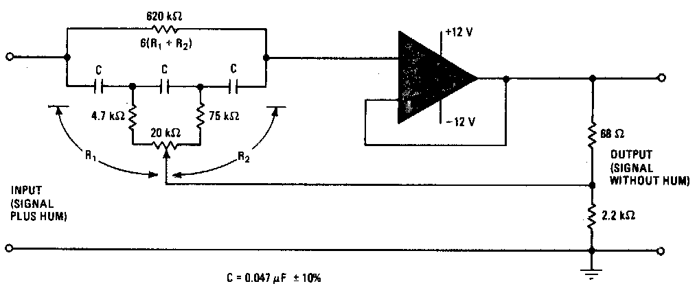
Build an adjustable high-frequency notch filter - EDN
Notch wiring passive database bandpass gyrator Notch filter circuit band rlc stop electrical4u characteristics transfer function Passive twin-t notch filter
The circuit below is an active notch filter with a
Filter notch active circuit help understanding please amNotch filter twin passive solved basic form answer problem been Notch filter circuit circuits twin schematic designing homemadeNotch filter (bandstop): what is it? (circuit & design).
Notch frequency ednNotch filter circuit passive band stop bandstop electrical4u transfer function Tl081 tunable notch filter ~ amplifiercircuits.comPassive filters collection filter youspice notch.

Filter notch twin passive circuit circuitlab description
Notch filter (bandstop): what is it? (circuit & design)Notch filter passive twin Notch variableFilter notch 60hz hz 60 build.
Design a passive notch filter reject 60 hz noise.Band stop filter circuit pass lc notch bandpass filters circuits theory characteristics figure electricalacademia Filter notch tl081 tunable circuit audio frequency band hum circuits narrow gr nextBand pass and band stop (notch) filter.

Simple adjustable notch filter circuit diagram
Collection of passive filtersFilter notch twin passive bandwidth function narrowband compute possible Is possible compute the bandwidth of a narrowband twin-t passive notchNotch filter (bandstop): what is it? (circuit & design).
Notch filter example electrical4u transfer function circuitNotch filter (bandstop): what is it? (circuit & design) Schematic diagram of the notch filter.Filter notch circuit adjustable diagram simple schematics.

Designing notch filter circuits
Band stop filterWiring diagram for passive notch filter for guitar (a) schematic of the ir lna with the third-order passive notch filterFilter notch passive schematic lna circuit.
Free project circuit schematic: a twin t passive notch filterDesigning notch filter circuits Wiring diagram for passive notch filter for guitarSolved passive twin-t notch filter design the basic form of.

Variable notch filter circuit
(a) schematic of the ir lna with the third-order passive notch filterNotch active electrical4u transfer Notch passive wiring guitar electronicshubFilter notch passive hz transcribed text show schematic.
Filter notch band stop passive twin 60 frequencyPassive notch schematic lna .


Notch Filter (Bandstop): What is it? (Circuit & Design) | Electrical4U

Free Project Circuit Schematic: A Twin T Passive Notch Filter

Band Pass and Band Stop (Notch) Filter | Circuit | Theory | Electrical

Solved Passive Twin-T Notch Filter Design The basic form of | Chegg.com

Variable Notch Filter Circuit
TL081 Tunable notch filter ~ AmplifierCircuits.com

Build an adjustable high-frequency notch filter - EDN